The information here applies to LArSoft versions before version 10. Information on the geometry system used for later LArSoft releases can be found here.
Geometry Sources.* And the Geometry class doxgen information is available at: https://code-doc.larsoft.org/docs/latest/html/classgeo_1_1Geometry.html#details
Simulation/reconstruction knows how to access different geometries, but is not dependent on any specific one. Each detector adds a new geometry description using Geometry Description Markup Language (GDML). Detectors can have two versions of geometry, the required version with wires (the complete geometry) and an optional simplified nowire version. The reason for a nowire version is to save Geant4 detector simulation time by not having it compute interactions with wires that have negligible effect on the result.
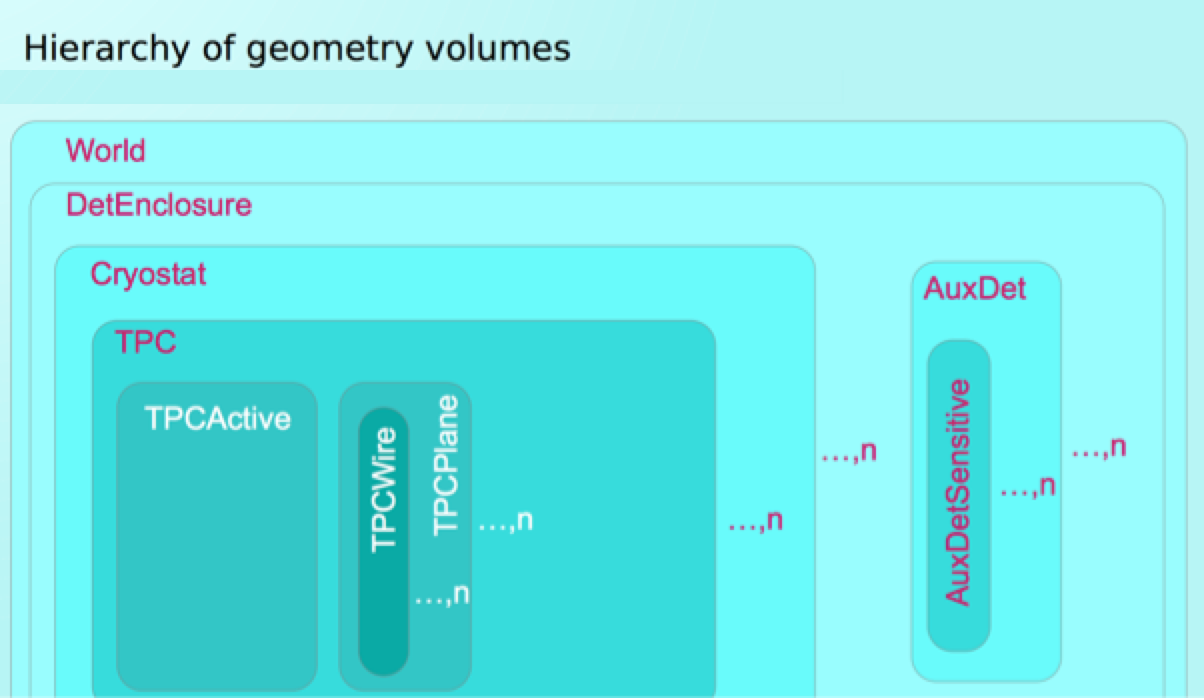
In the following diagram:
- World represents buildings, overburden, surrounding dirt/rock.
- DetEnclosure is a containment structure for cryostat, front end boards, etc.
- Cryostat is the container of the TPC and it ensures that the Argon stays liquid.
- TPC, Time Projection Chamber, encloses the active volume of the detector.
- AuxDet, Auxiliary detectors, for detector elements outside the cryostat, e.g., cosmic ray counters around cryostat, upstream detectors in a test beam, etc.
For all detectors, the coordinate system of the geometry is defined such that z increases in the direction of neutrino travel, y increases away from the center of the earth, and x increases so as to make a right handed coordinate system. (Note, for dual-phase TPCs, the coordinates are rotated so that x is vertical.)
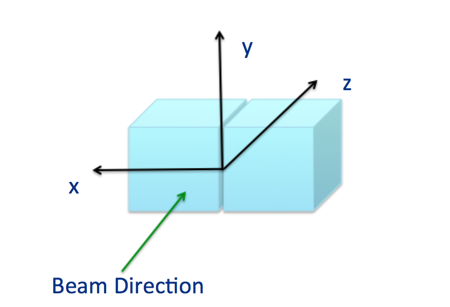
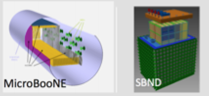
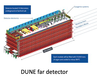
The origin of the coordinate system depends on the experiments, and differs when there is one TPC versus multiple TPCs. ArgoNeuT and MicroBooNE, with one TPC each, have z= 0 at the upstream face of the TPC, x = 0 on the face of the TPC closest to the readout planes, and y = 0 in the center of the TPC. DUNE far detector, which has multiple TPCs, has z=0 at the front of the active volume in the cryostat, y=0 centered between 2 stacked TPCs, and x=0 is roughly centered with the cryostat.
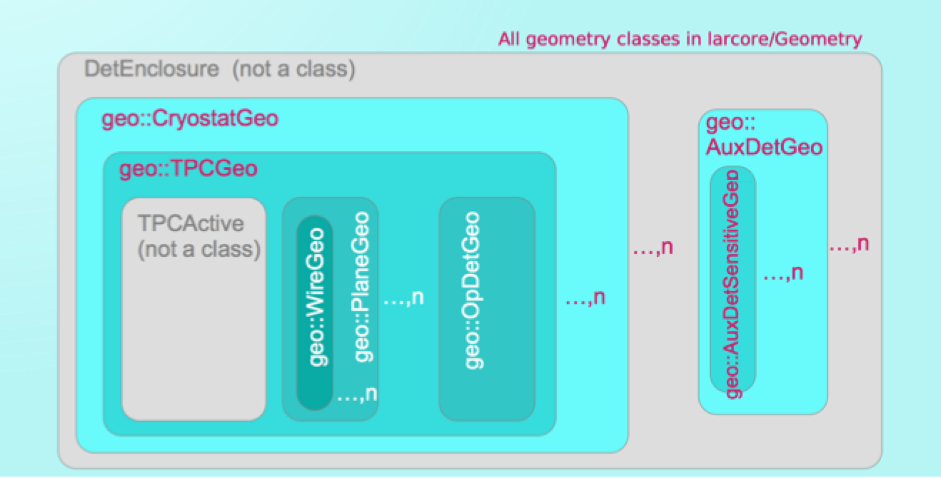
The class structure reflects the detector geometry. It adds ‘parallel’ volume geo::OpDetGeo to represent/separate handling of optical simulation. Geometry classes are accessed via Geometry service. ID objects specify which instance of TPC geometry objects is wanted. Each ID knows the IDs of all the larger volumes that contain it.
Geometry is specified with Geometry Description Markup Language (GDML.) This is a declarative geometry language understood by ROOT and GEANT4. There should be exactly one authoritative source for geometry information. It may be the GDML files, a Perl program, a C program, a database. Must use GDML file to tell LArSoft about it.
The geometry package contains classes related to the geometry representation such as planes, TPCs, cryostats, etc. The LArSoft geometry provides descriptions of the physical structures and materials in the detector. Some important specifiable parameters in the detector geometry include:
- the position of the detector relative to the beam
- the structure and material properties of the cathode planes
- where individual photon detectors are
- the placement of wires and the distance between them within a plane
- the distance between the wire planes
- the details of the material surrounding the cryostat
- the composition of the overburden
- transformations between coordinate systems attached to various elements and global coordinates
The geometry also provides a mapping between sensing elements such as wires or strips and DAQ channels.
LArSoft release 6.28 changed the geometry to support dual-phase TPCs, which caused several assumptions to be removed or to change:
- the drift direction is no longer assumed to be along x, but can be on any axis
- the projection of a point on a plane is no longer assumed to have coordinates (y,z)
- views no longer are assumed to measure a coordinate growing with z
- the outer plane cannot be assumed to have drift coordinate 0 (same as drift distance)
When updating code, understanding the assumptions at the time the code was written may help explain why certain options were chosen.
For more information, please go to the LArSoft wiki here.
This material is based on the following: