The information here applies to LArSoft v10+.For more detailed information, see the LArSoft wiki page for geometry users and developers. Geometry class doxgen information is available at: https://code-doc.larsoft.org/docs/latest/html/classgeo_1_1Geometry.htmlInformation on the legacy geometry system used for earlier LArSoft releases can be found here.
The LArSoft simulation and reconstruction algorithms use the LArSoft geometry system to access geometry information for many different detectors without being dependent on any specific one. The system supports detector independence by factoring the overall geometry description into several sub-systems, where each describes a set of common features through a shared interface across one or more types of LArTPC detector elements. Different experiments then provide distinct configurations for each of the relevant sub-systems to yield fully detector-specific run-time geometry descriptions. Owing to this structure and the many common features of LArTPCs and their readout schemes, the geometry system can accommodate a wide range of detectors, such as those in Fig. 1 below.
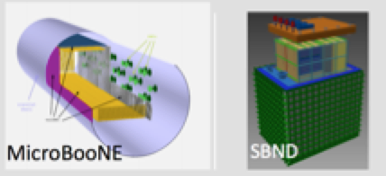
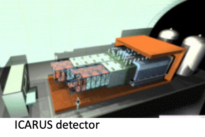
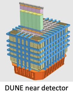
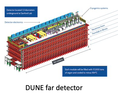 Figure 1: Detectors
The sub-systems within the geometry system are the following:
- A core volume hierarchy that reflects the segmentation of an experimental area into cryostats and their contained TPCs and photo-detector systems. Details specific to TPCs or photo-detectors are available at via this hierarchy. The volumes and shapes, represented by Root geometry objects, are also accessible. This sub-system also provides tools for navigating the hierarchy and iterating over detector elements.
- A set of readout geometries that describe the details of physical readout structures and the associated electronics channels for each TPC. Two different types of readout geometries are supported, one for detectors using wire-based charge sensing and readout, and a second for detectors using pixel-based charge sensing and collection. Each type can be used for any detector employing that type of readout. This sub-system also provides tools for navigating and iterating over the readout structures, as well as a mapping between physical readout elements and logical readout channels.
- An auxiliary detector system used to represent detectors outside the cryostats that may be used in conjunction with the LArTPC detectors, but that are not part of LArSoft, such as scintilator-based cosmic ray taggers surrounding a cryostat. Geant4 simulations will deposit energy in any sensitive volume defined for these detectors, but experiment-specific code will be needed for any detector response simulation or data reconstruction.
The initialization of the above subsystems is driven by the contents of a detector-specific GDML file, and a combination of generic and detector-specific initialization algorithms.
Algorithms that access the geometry must retrieve the interface classes for each of the sub-systems required for the algorithm in question.
The geometry also supports various types of external detectors of specific types. The software needed to simulate and reconstruct auxiliary and external detectors is experiment specific, so is not a part of LArSoft.
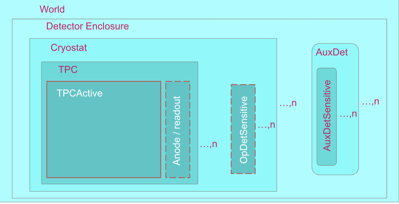
Figure 2 shows the basic, generic conceptual volume hierarchy that is common to all LArTPC experiments and is represented in the full geometry description:
- World contains everything in the geometry, including buildings, overburden, surrounding dirt/rock.
- Detector Enclosure is the nominal volume inside the World that represents the containment structure for cryostat(s), readout electronics, cryogenic systems, etc.
- Cryostat contains theTPCs and photo-detectors and ensures that the Argon stays liquid.
- TPC is the idealized volume that defines the logical detector volume, and includes the active volume of the detector (the region between the cathode plane and anode region). It is typically bounded by the anode and cathode planes and the field cage. Exceptions include cases where the volume within the field cage is sub-divided into multiple logical TPCs, or where there are sensitive regions behind the anode.
- Optical detectors are typically included inside the cryostat, but outside the TPCs. Both the sensitive volume for photo-detectors and other physical structures can be included in the overall description. Only the sensitive volumes are represented in LArSoft.
- AuxDet, Auxiliary detectors, for detector elements outside the cryostat, e.g., cosmic ray counters around cryostat, upstream detectors in a test beam, etc.
For all detectors, the coordinate system of the geometry is defined such that z increases in the direction of neutrino travel, y increases away from the center of the earth, and x increases so as to make a right handed coordinate system.
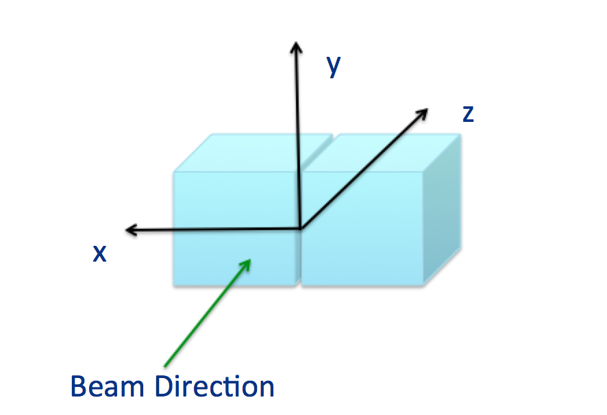
The origin of the coordinate system depends on the experiments. For instance, ArgoNeuT and MicroBooNE, each with one LArTPC, have z= 0 at the upstream face of the TPC, x = 0 on the face of the TPC closest to the readout planes, and y = 0 in the center of the TPC. ICARUS places x=0 between opposing TPCs such that one TPC drifts in the negative-x direction, the other in the positive-x direction.
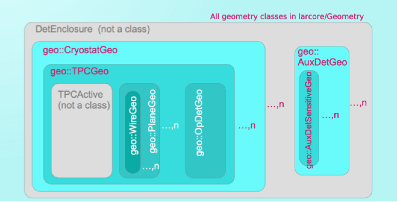
The class structure reflects the detector geometry. Geometry classes are accessed via Geometry service. ID objects specify which instance of TPC geometry objects is wanted. Each ID knows the IDs of all the larger volumes that contain it.
The Geometry is specified with GDML, a declarative geometry language understood by ROOT and GEANT4. There should be exactly one authoritative source for geometry information. It may be the GDML files, a Perl program, a C program, a database. In all cases, a GDML file is used to tell LArSoft about it.
The geometry package contains classes related to the geometry representation such as planes, TPCs, cryostats, etc. The LArSoft geometry provides descriptions of the physical structures and materials in the detector. Some important specifiable parameters in the detector geometry include:
- the position of the detector relative to the beam
- the structure and material properties of the cathode planes
- where individual photon detectors are
- the placement of wires and the distance between them within a plane
- the distance between the wire planes
- the details of the material surrounding the cryostat
- the composition of the overburden
- transformations between coordinate systems attached to various elements and global coordinates
The geometry also provides a mapping between sensing elements such as wires or strips and DAQ channels.
For more information, please see the following:
- Introduction to LArSoft – source material
- Detailed wiki page on V10+ Geometry
- Video recording of Geometry Refactorization presentation at LArSoft Coordination Meeting in February of 2024